BIT-C-128
Video DAC for Commodore 128/128D, IBM CGA, and Tandy CGA Plus
Uses for the BIT-C-128 Video DAC
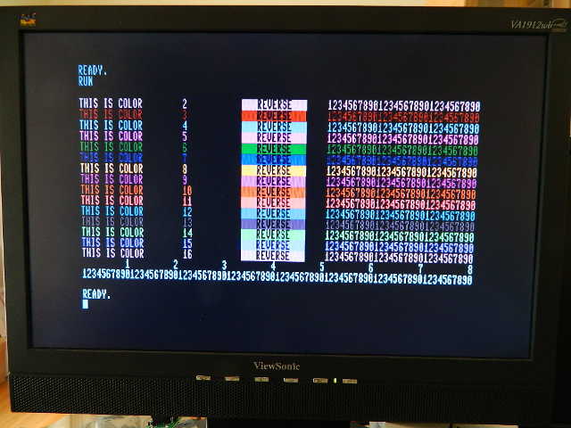
The most common application for the BIT-C-128 Video DAC is driving a VGA display through a low-cost video scaler such as a Gonbes GBS-8200 or GBS-8220 video converter. (Sample output using this configuration is pictured below at right.)
Another useful application for the BIT-C-128 Video DAC is driving a pre-VGA (<17 kHz) analog RGB display, such as displays with BNC connectors or the Commodore 1084-D2, which accepts input from analog RGB but not digital RGBI signals.
Extending RGBI Video
Whichever way the BIT-C-128 Video DAC is used, it may be connected to the computer through an optional DE-9 extension cable. The length of such a cable should not exceed about 6 feet or 2 meters. Optional jackscrews are recommended to secure the cable to the BIT-C-128 Video DAC.
Driving an HDMI Display
There are a few ways to drive an HDMI display with an older computer. Though I hear good things about the Micomsoft Framemeister XRGB-Mini, I shy away from its $370 price.
If you want to drive an HDMI display inexpensively, you can add a Gana Link VGA to HDMI video converter (also available in white) to the 80-column VGA solution below for about $15.
If you can spare a second HDMI input, you can convert the 40-column output using a Gana Link composite video to HDMI video converter for only about another $20. (I expect you would get a better picture using the 40-column hookup using S-Video below, though it would cost about $60 more.)
Driving a VGA Display
The most common application for the BIT-C-128 Video DAC is driving a VGA display through a low-cost video scaler such as a Gonbes GBS-8200 or GBS-8220 video converter.
What you'll need:
- BIT-C-128 Video DAC
- Gonbes GBS-8220 (recommended) or GBS-8200 video converter with included cables
- A good AC adapter that supplies 5 volts DC at 2 amperes (to plug into the Gonbes video converter)
This combination will convert digital output from Commodore 128 and 128D computers in 80-column mode, IBM CGA, or Tandy CGA Plus and display it on a VGA monitor.
Using 40-Column Modes
Commodore 128 and 128D computers use a separate circuit to generate their 40-column video output, so the BIT-C-128 Video DAC is not needed to display 40-column video.
If you are using a Gonbes video converter, you can view 40-column output in grayscale preactically for free simply by adding a video cable to feed the luma (Y) signal (or—less ideally—the composite video signal) into the Y channel of the component video (YPbPr/YCbCr) input of the Gonbes unit, as shown below left.
Color from 40-column modes may be displayed by adding a component color separator such as the Ambery SDV1 (which sells for $80) and 3 RCA male-male cables (or a triple RCA cable), as shown below center and below right. The Ambery SDV1 may be connected to the Commodore 128 using a circular DIN cable with either S-Video (for sharpest display) or composite video (yellow RCA).
Note that the Commodore 128 may operate in either 40-column mode or 80-column mode, based on whether the "40/80 DISPLAY" key is set up (for 40 columns) or down (for 80 columns) when the computer is turned on or reset; Commodore 64 mode (40-column) may be entered from Commodore 128 modes (40-column or 80-column) by using the command "GO 64". For more information, see C128 System Guide - Section 2.
Switching the Gonbes unit's input (cycling through RGBS, RGBHV, and component) may be done by pressing its "SW" button, and switching the Ambry SDV1's inputs (between CVBS and S-Video) may be done by pressing its button.
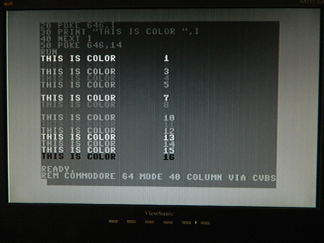
40-column Commodore 64 mode using composite video into Y channel of component input on GBS-8220, using:
- Gonbes GBS-8220
- AC adapter for GBS-8220
- Commodore circular DIN to composite video (RCA) cable
|
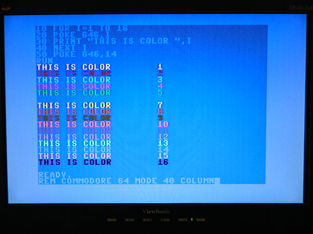
40-column Commodore 64 mode using composite video via Ambery SDV1 component output to GBS-8220, using:
- Gonbes GBS-8220
- AC adapter for GBS-8220
- Commodore circular DIN to S-Video cable
- Ambery SDV1 (with included AC adapter)
- 3 RCA male-male cables (for component video)
|
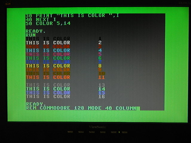
40-column Commodore 128 mode using composite video via Ambery SDV1 component output to GBS-8220, using:
- Gonbes GBS-8220
- AC adapter for GBS-8220
- Commodore circular DIN to S-Video cable
- Ambery SDV1 (with included AC adapter)
- 3 RCA male-male cables (for component video)
|
Driving an Analog RGB Display
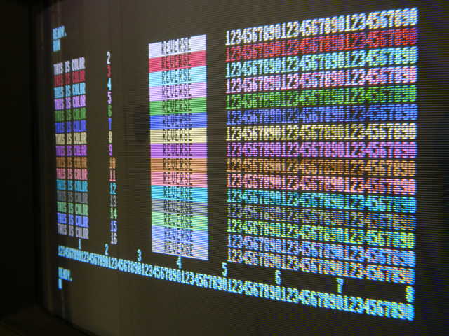
The BIT-C-128 Video DAC may also be used to drive pre-VGA (<17 kHz) analog display directly.
Use of an analog CRT (such as the one pictured at right) demonstrates the BIT-C-128 Video DAC's high signal quality, including the accuracy of its colors and the sharpness of the characters.
Driving an RGB Display with BNC Inputs
The BIT-C-128 Video DAC has been tested driving the analog RGB and composite sync inputs of a Sony PVM-1342Q, as pictured at right. (Note that the PVM-1342Q also has a digital RGBI input that a Commodore 128 can drive directly using only an extension cable with DE-9 connectors, although the colors displayed will differ slightly without the BIT-C-128 Video DAC.)
Driving a display like this, the BIT-C-128 Video DAC will need a source of 5-volt power, such as from a USB port or power adapter.
For the easiest and nicest solution, here's what you'll want:
- BIT-C-128 Video DAC
- AC adapter that supplies 5 volts
- 2-wire connector kit for the AC adapter
- VGA-to-BNC cable
- 6-wire connector kit for the VGA-to-BNC cable
- Pair of long hex nuts to mate the VGA-to-BNC cable to the connector kit
To Make Your Own Cables
If you would like to solder your own wire connections, here's how:
| Kit | Wire
Color | Connector
Pin | Function |
|---|
| power | red | center | +5V DC power supply |
| black; | outside | power supply return ("ground") |
6-wire
signal | black | 6,7,8 * | signal return ("ground") |
| yellow | 14 | vertical sync |
| gray ** | 13 | horizontal sync (jumper removed) or composite sync (jumper present) |
| red | 1 | red channel analog output |
| green | 2 | green channel analog output |
| blue | 3 | blue channel analog output |
* VGA signal return ("ground") pins are 5 (digital horizontal sync return), 6 (analog red return), 7 (analog green return), 8 (analog blue return), and 10 (digital return for vertical sync/blank and VESA DDC). For best performance, connection to only analog signal returns (pins 6, 7, and 8) is recommended.
** Gray wire used on Gonbes cables. Color may vary on 6-wire kit.
I highly recommend sealing each connection with heat-shrink tubing and adding strain relief to the wires coming from the D connector, as I do.
Driving a Commodore 1084-D2 Display
The Commodore 1084-D2 display accepts input from analog RGB but not digital RGBI signals. (Other versions of the 1084 display include a locking pushbutton switch on the rear panel that allows selection of RGB analog or RGBI digital inputs via their DE-9 connectors.)
There are a couple of easy ways to connect a Commodore 1084-D2 display.
You could buy or build an adapter and connect it like this:
| Kit | Wire
Color | Connector
Pin | Function |
|---|
| power | red | center | +5V DC power supply |
| black; | outside | power supply return ("ground") |
5-wire
signal | black | 1,2 | signal return ("ground") |
| gray * | 7 | composite sync (jumper present) |
| red | 3 | red channel analog output |
| green | 4 | green channel analog output |
| blue | 5 | blue channel analog output |
* Color may vary.
Alternately, you could cut a DE-9 extension cable and connect the wires like this:
| Kit | Wire
Color | Connector
Pin | Function |
|---|
| power | red | center | +5V DC power supply |
| black; | outside | power supply return ("ground") |
DE-9
cable | brown | 1 | signal return ("ground")* |
| red | 2 |
| orange | 3 | red channel analog output |
| yellow | 4 | green channel analog output |
| green | 5 | blue channel analog output |
| violet | 7 | composite sync (jumper present) |
* Either or both return wire(s) may be connected to the BIT-C-128 Video DAC.


